
System Optimiser Quick Start#
Welcome to System Optimiser! This short guide can be thought of as a walkthrough for building a simple loudspeaker system design. It does not cover all functions of the application, but is a good place to start for quickly measuring a venue and designing sources.
Running System Optimiser for the First Time
After downloading the latest version from www.codaaudio.com, follow the installation instructions in this documentation.
Upon launching System Optimiser for the first time, you will be asked to accept the EULA, and then the Data Version Manager will open. The latest dataset must be downloaded and then selected with the radio button in the ‘Use’ column.
Drawing a Basic Theatre
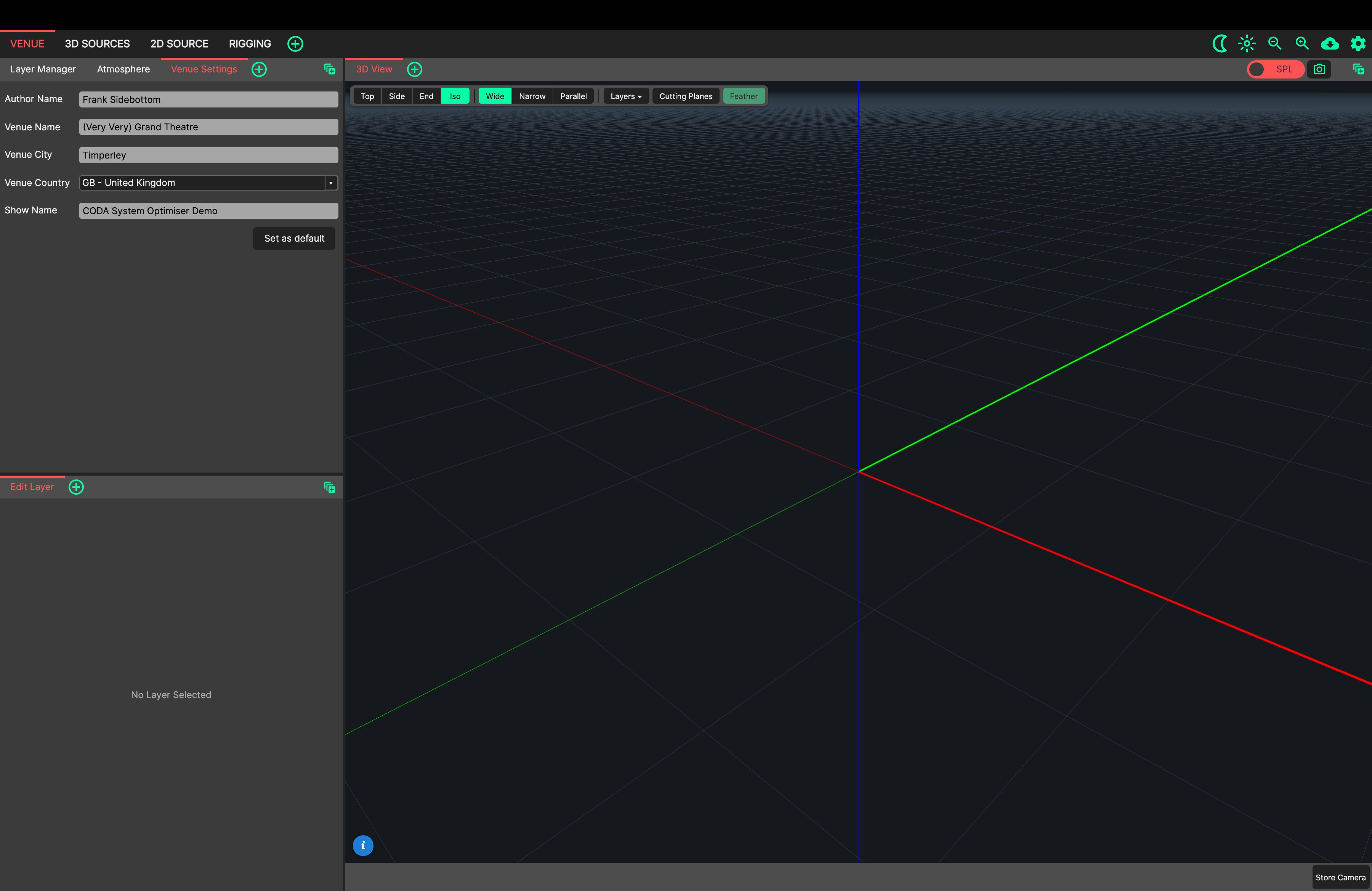
Let’s start by filling in some useful information in the Venue Settings Panel. This is open by default in the VENUE tab.
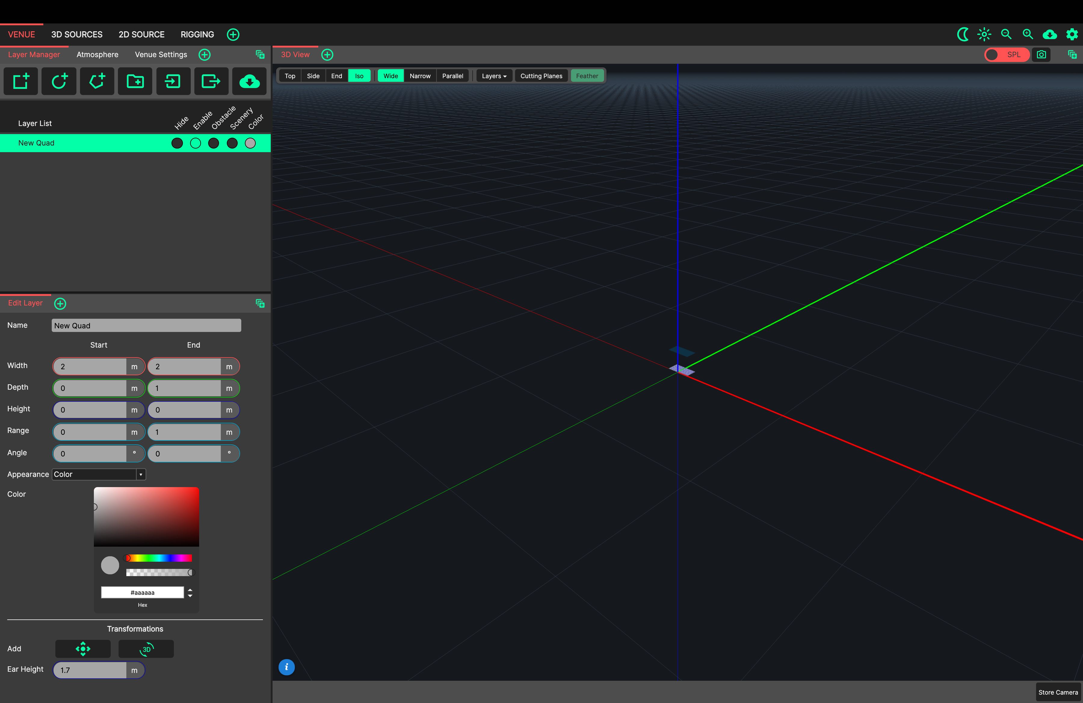
Next, we’ll use the Layer Manager to create our first section of geometry in the 3D View.
We’re describing a rectangular theatre with stalls and a balcony. For this, we’ll use a Quad. Create one by clicking its button in the top bar of the Layer Manager. It’s the first button from the left - a square with a green ‘plus’ icon. The new Quad is shown in the Edit Layer Panel, below the Layer Manager, where we’ll enter its values.
The venue is 23m wide at the end closest to the stage. We’ll use this as our Start ‘Width’ entry.
The venue is 39m wide at the back of the stalls. We’ll use this as our End ‘Width’ entry.
The stalls start at the downstage edge, so we’ll enter our Start ‘Depth’ as 0m.
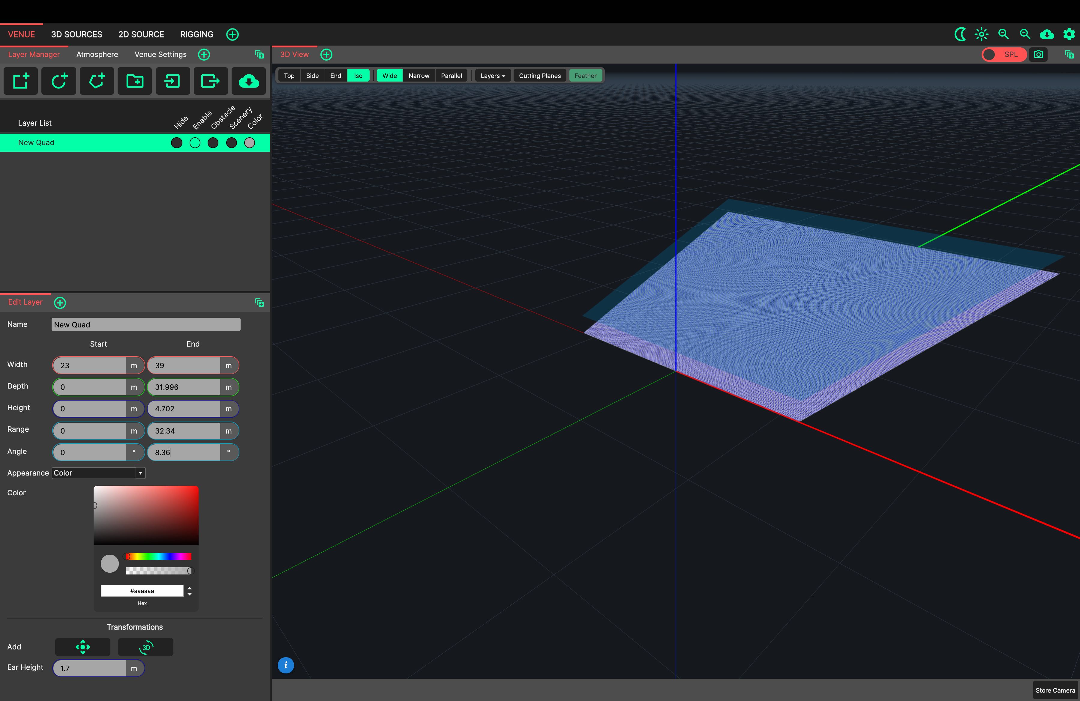
Next, we’ll use our laser rangefinder/inclinometer to quickly measure the audience area. We’ll take a measurement at each point that a surface transitions into another, for example, where the stalls transition into the back wall of the venue.
We’ll enter our information in ‘Angular’ terms. System Optimiser allows for traditional ‘Cartesian’ data entry (Height and Depth) at the same time as ‘Angular’ input (Range - the distance of a point away from the measurer - and Angle - the incline of the line between the measurer and the point).
We will name this Quad ‘Stalls’, and enter an Ear Height of 1.2m (seated).
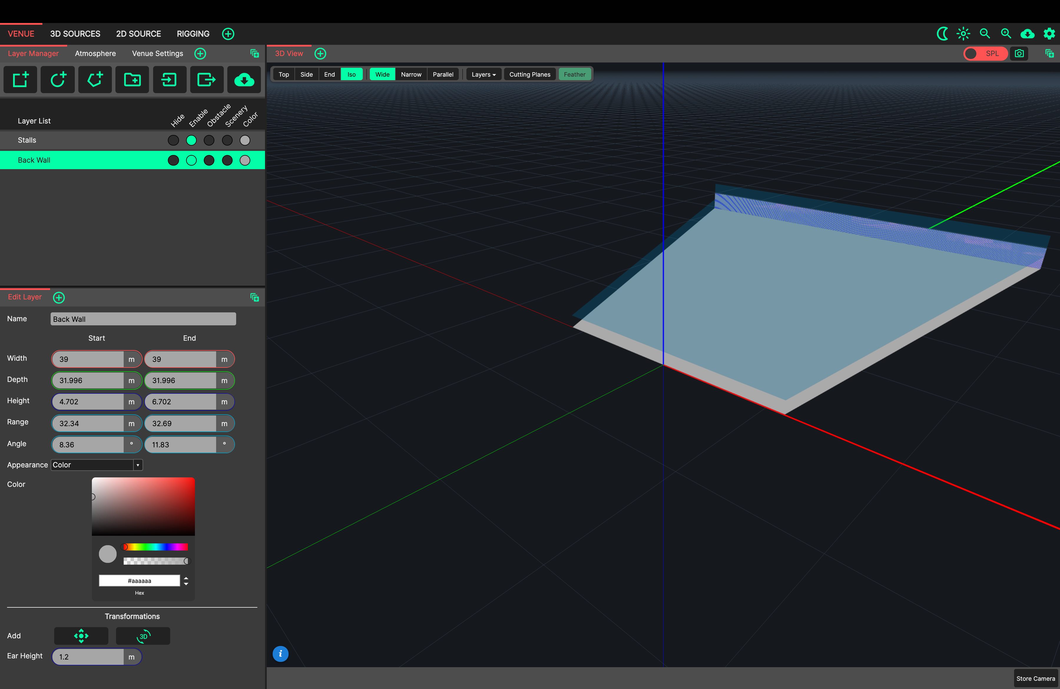
To save entering the measurements for the back of the stalls again when starting our next Quad, we’ll use the ‘Continue Layer’ function by right-clicking our ‘Stalls’ layer and selecting ‘Continue Layer’ from the list.
This has created a new Quad, using the ‘End’ coordinates from the ‘Stalls’ layer we created as our new ‘Start’ coordinates, and shown it in the Edit Layer Panel.
Rename this from ‘Continue of Stalls’ to ‘Back Wall’.
We’ll enter our next measurement as the End ‘Range’ and ‘Angle’, taken from the top of the back wall.
32.69m, at +11.83°
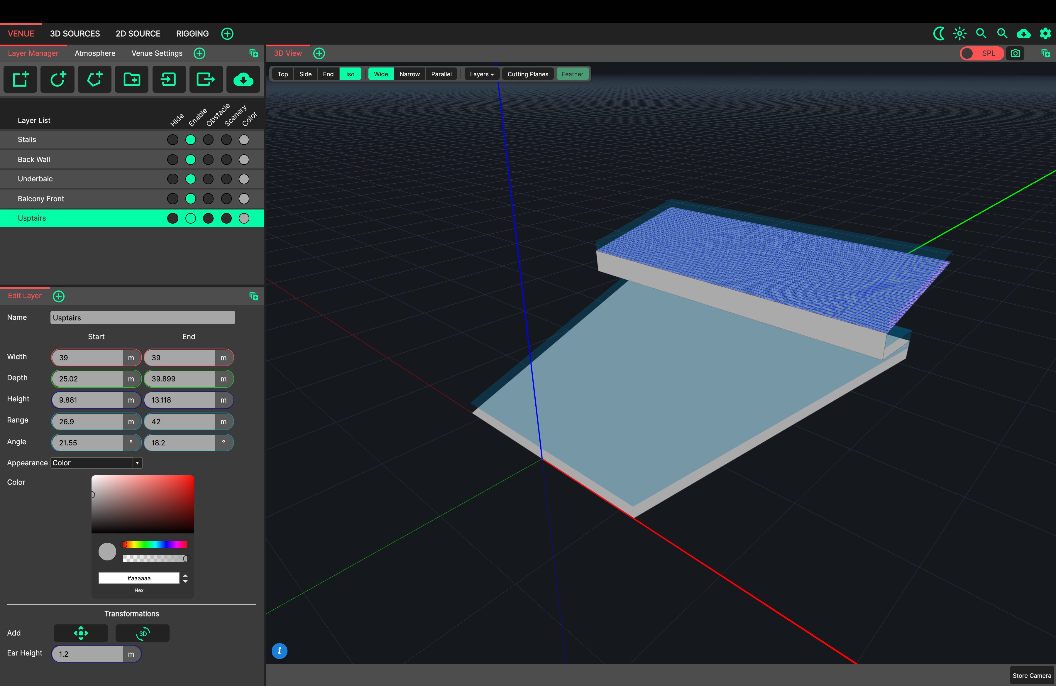
We’ll keep using this method of ‘Continuing’ each layer to enter the following values:
26.2m, at +15.7°
26.9m, at +21.55°
42m, at +18.2°
Each time, the ‘End’ coordinate is edited after using ‘Continue’ from the previous layer.
Give an appropriate name to the new layers created.
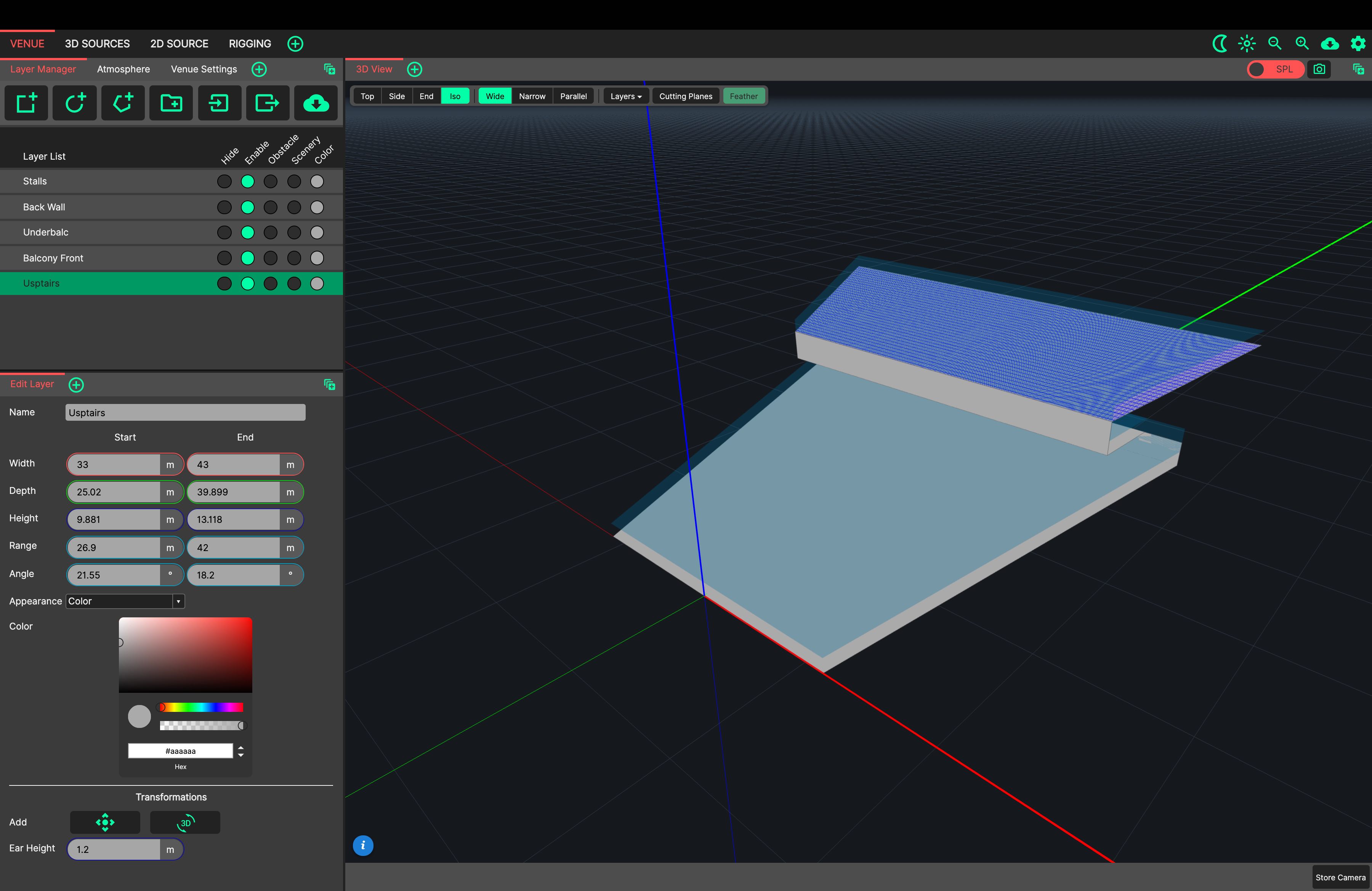
Let’s tweak the balcony we have created.
The balcony measures 33m in width at the front, closest to the stage, and 43m in width at the back. Click each layer in the Layer Manager to show it in the Edit Layer Panel, and adjust the Start and End ‘Width’ for the balcony layer, and for the balcony front and stalls ceiling created.
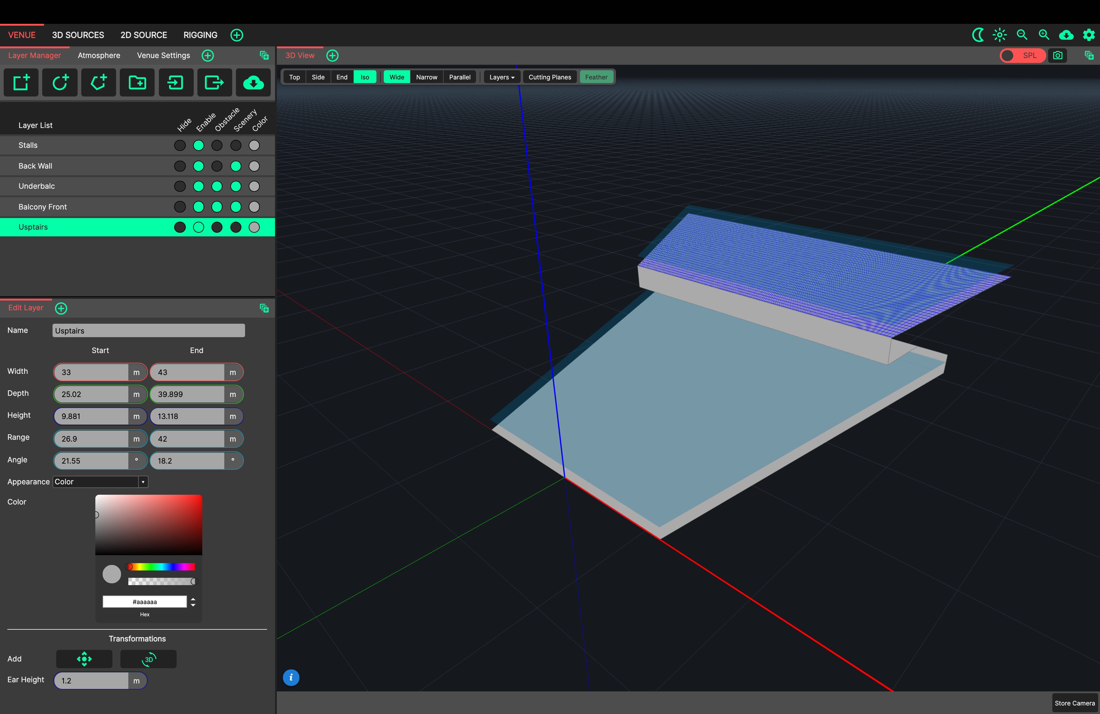
Finally, let’s tag the back wall, stalls ceiling and balcony front as Scenery using the Layer Properties toggles in the Layer Manager.
We’ll also tag the ceiling and balcony front as an Obstacle.
This will remove the Audience Ear Heights from these layers, and ensure that they cast a shadow in the 3D View.
Designing a Loudspeaker System
Let’s switch to the 3D SOURCES tab with Ctrl/Cmd+2.
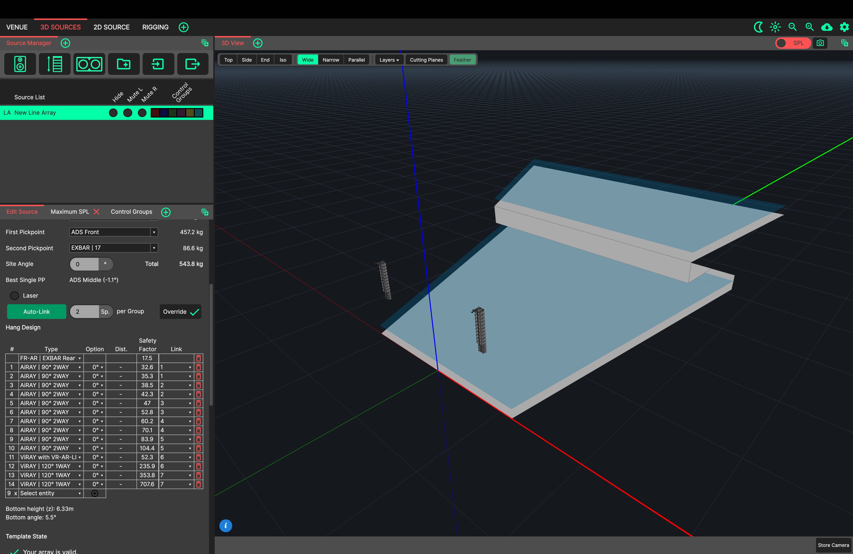
Create a new SVA (Standard Vertical Array) using the second button on the Source Manager’s top bar. Its controller is shown in the Edit Source Panel, below the Source Manager. We can name our source ‘Main Hangs’ and set its arrangement to stereo.
Let’s set our position to: X = 8m, Y = 0m, Z = 11m.
We can then use the Hang Template’s Frame Family and pickpoint settings to choose an FR-AR Frame with an EXBAR to the rear.
We’ll add loudspeakers to the array in the following order:
10x AiRAY (90°, 2-way)
1x ViRAY (120°, 1-way) with VR-AR-Link
3x ViRAY (120°, 1-way)
Clicking ‘Auto-Link’ will link our speakers in pairs.
Now switch to the 2D SOURCE tab with Ctrl/Cmd+3, and select ‘Main Hangs’ by clicking its row in the Source Manager - clicking the same row again cycles between the left and right hang.
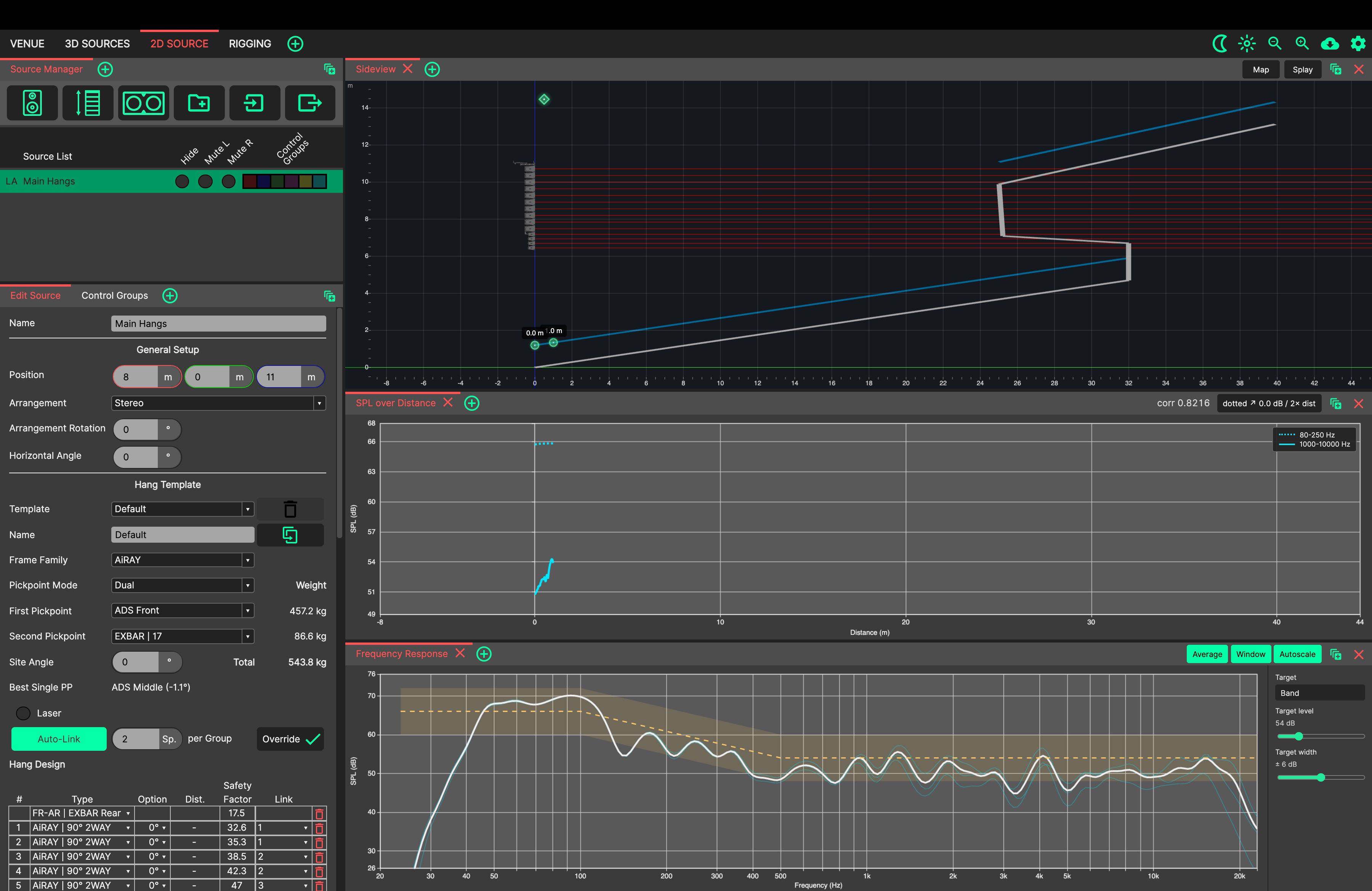
In the Sideview, drag the green circular markers to define the audience area to be covered.
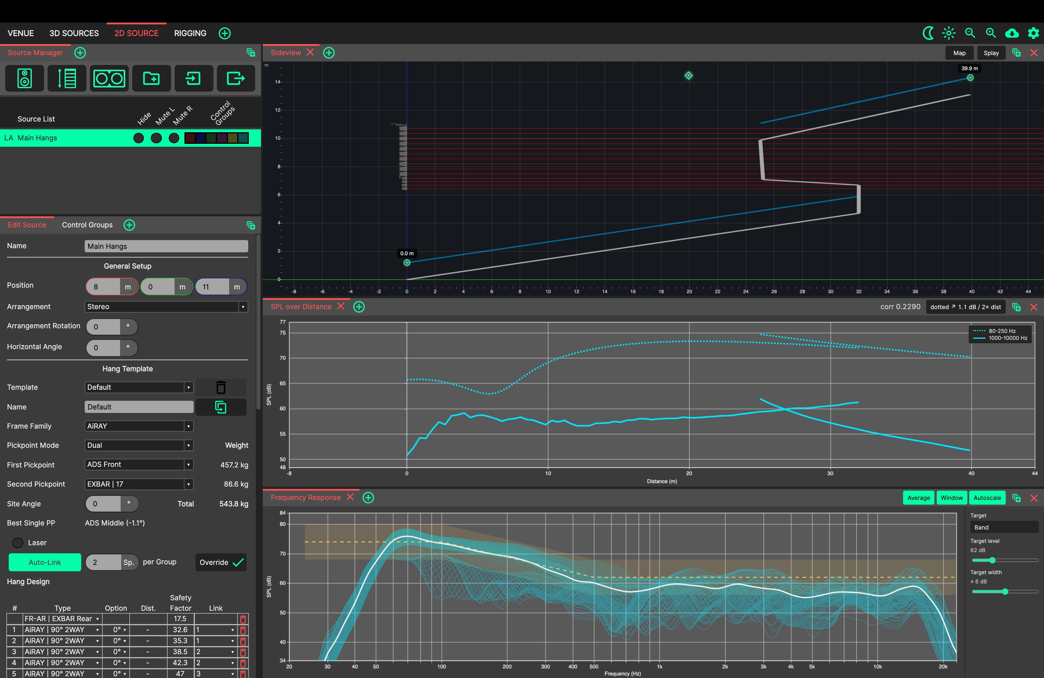
Click the Splay button in the Sideview. The array will automatically splay the angles to cover the desired coverage area.
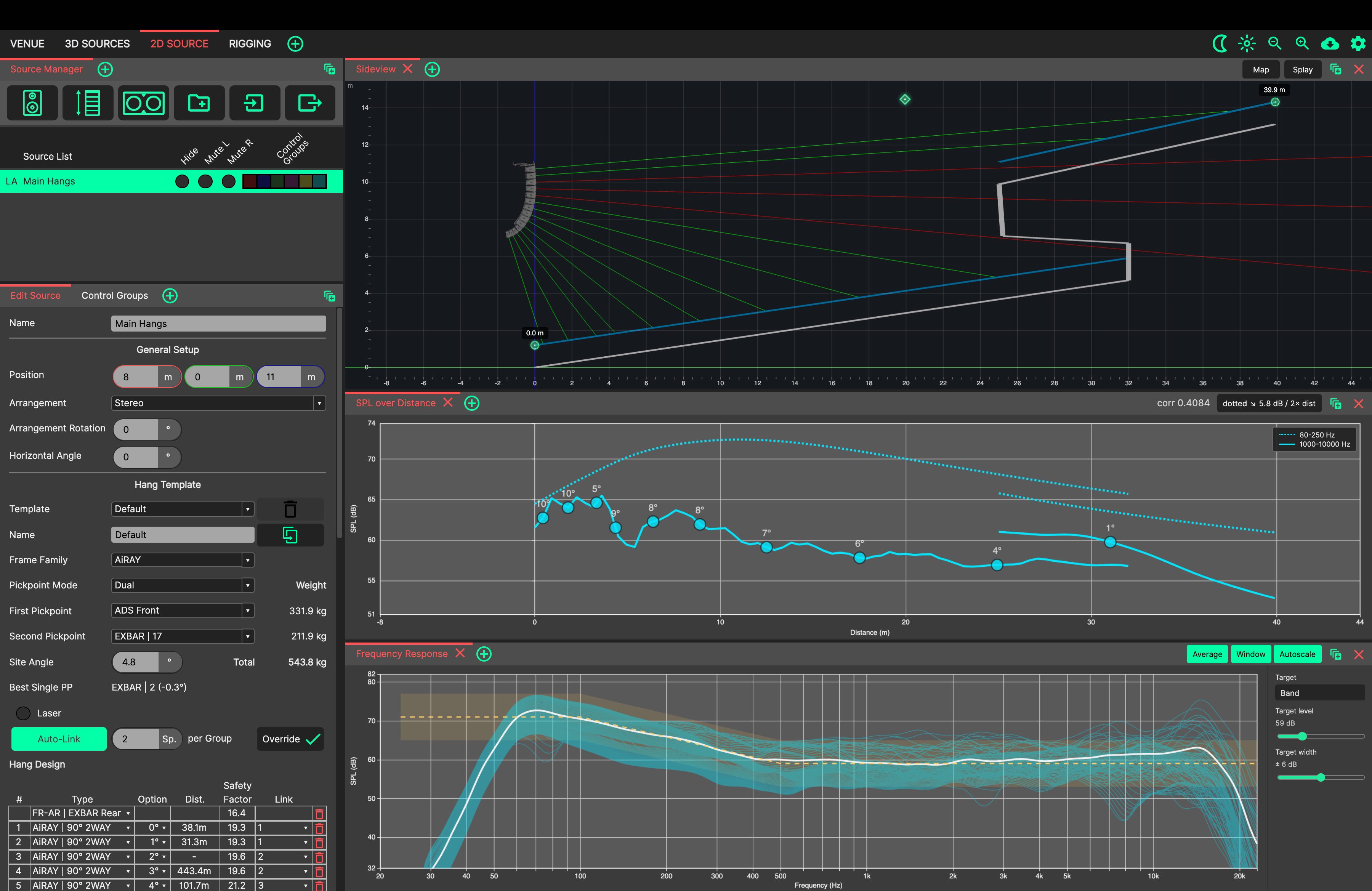
Click and drag the topmost throw line, to adjust the Site Angle of the array. Set it to overshoot the rear of the balcony on the audience slightly.
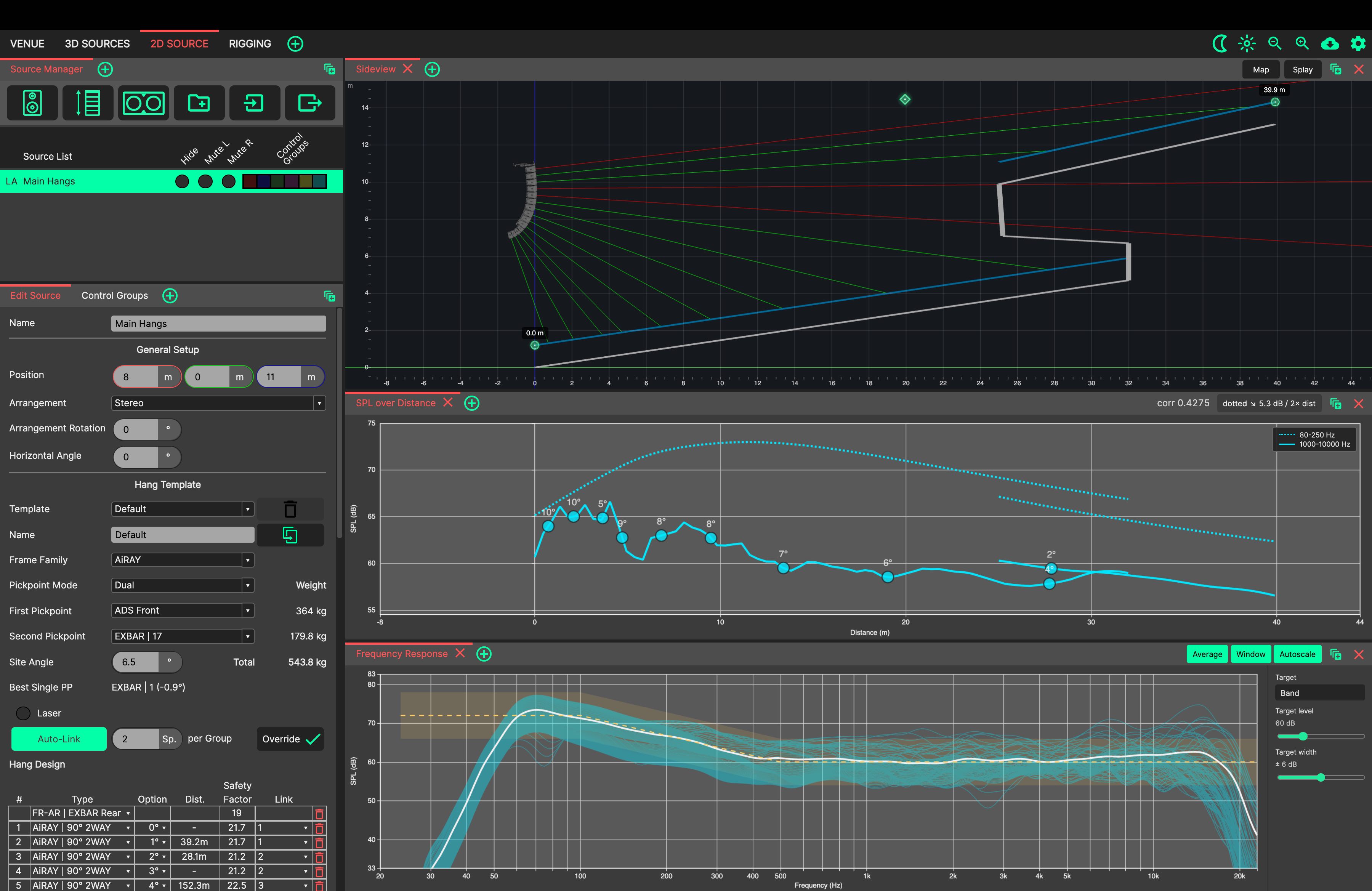
Click the topmost throw line, to ‘lock’ it into position (so that the Splay tool won’t touch it). Note that one of the markers disappears, for you can now only adjust the coverage start point - the end point is defined by the locked enclosure. Press ‘Splay’ again. Note - this lock can be used on any quantity of loudspeakers within the array, to prevent the Splay tool from ever adjusting them - useful for off-axis overshooting.
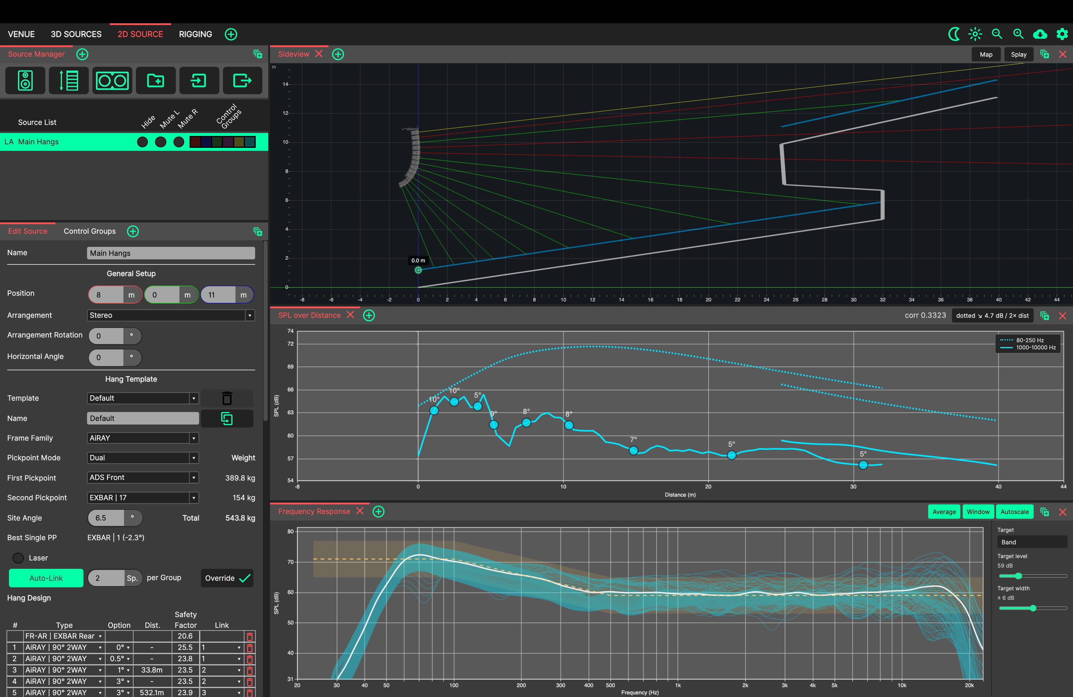
To see the result in the vertical plane, click Map in the Sideview’s header: the SPL of the array is mapped across the whole plane. Click Δ Hold before changing an angle (or before pressing ‘Splay’ again), and the map shows exactly where the coverage gained or lost level.
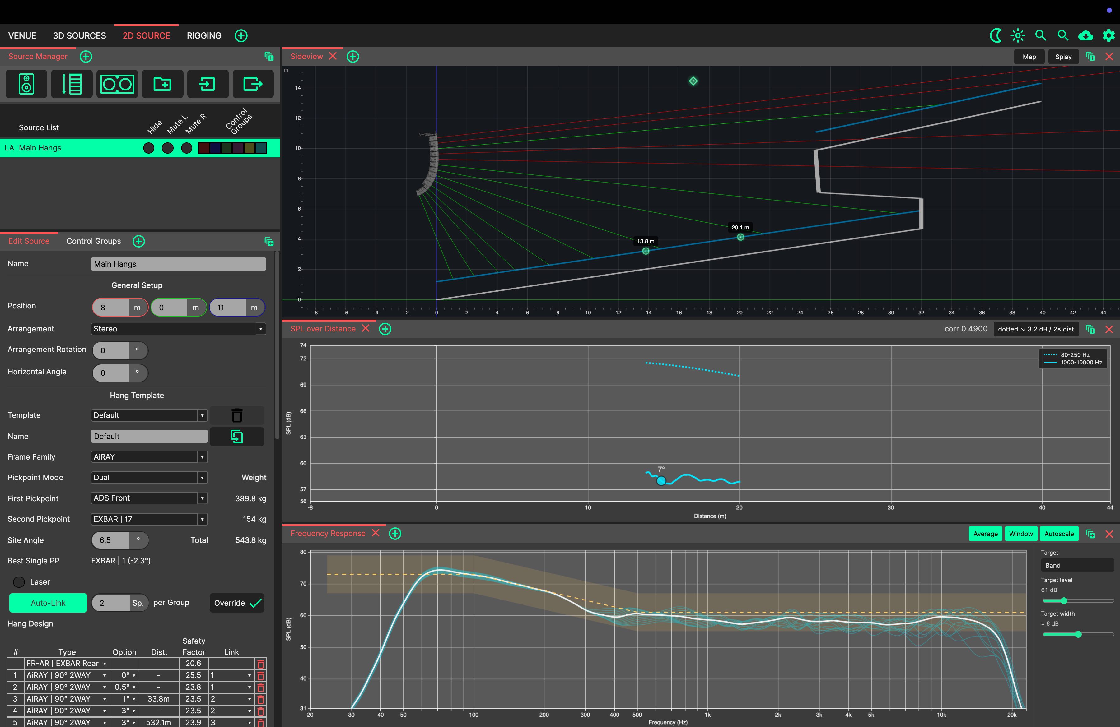
Unlock the loudspeakers (click the topmost yellow throw line until it is no longer selected). This will enable both the start and end markers once again. Drag these to an area of interest to inspect the frequency response at that point in space. Use the diamond above the two markers, to move them simultaneously.
Switch to viewing the Frequency Response Panel, which is already open next to the Sideview. It plots the frequency response at points sampled along the audience for our selected array - the Average button shows an energy-averaged mean curve across them.
Use the Frequency Response Panel to refine the splay angles in the SVA Controller for the smoothest response. The HF Shelf and Distance Filter can also be adjusted for optimisation using the Link Groups table.
Switch back to the 3D SOURCES tab view. You will now see the ‘Aim Discs’ which show the coverage of the loudspeaker system, and the throw lines of the selected source.
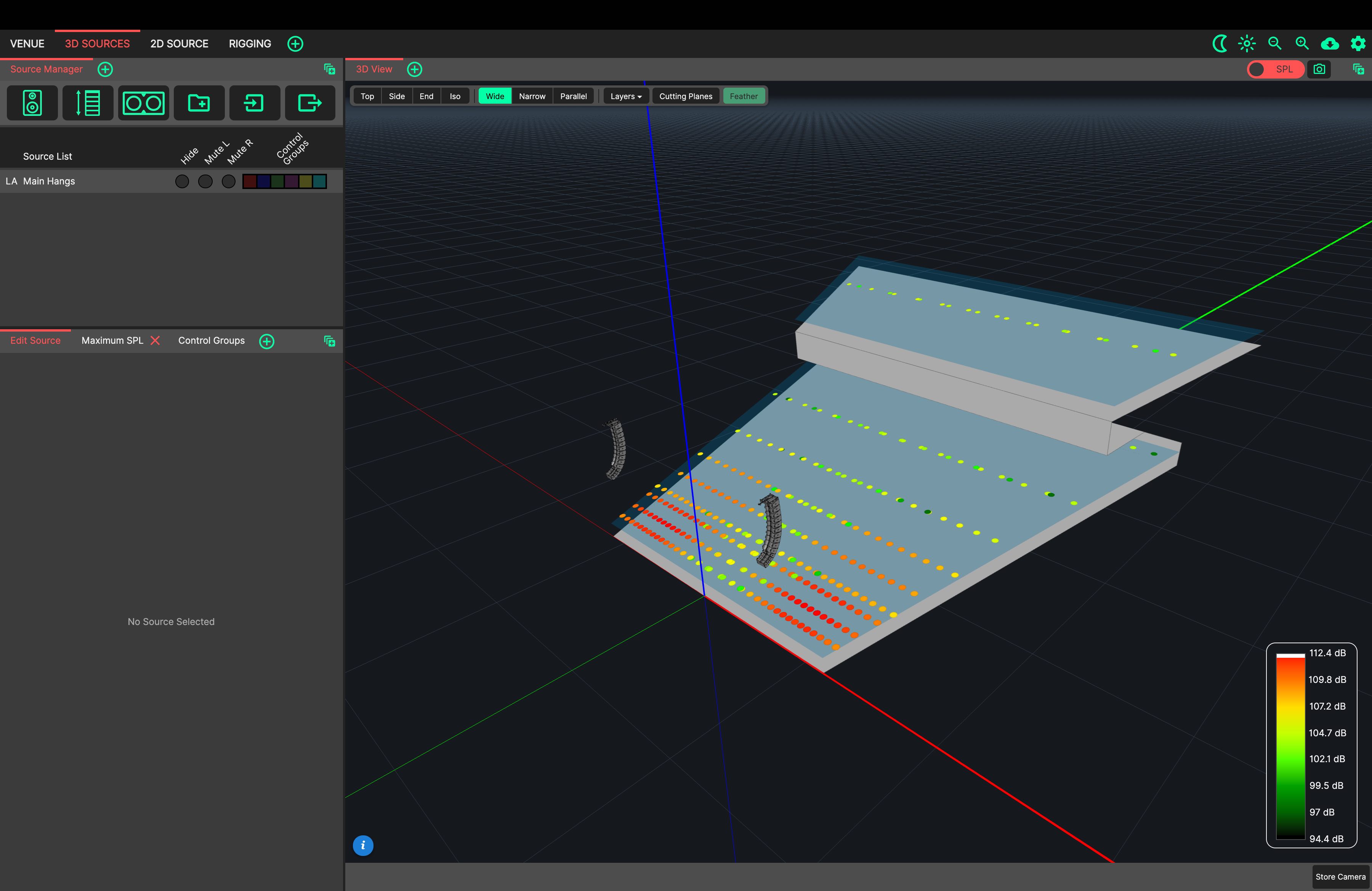
Using the third button in the Source Manager’s top bar, create a new HSA (Horizontal Subwoofer Array).
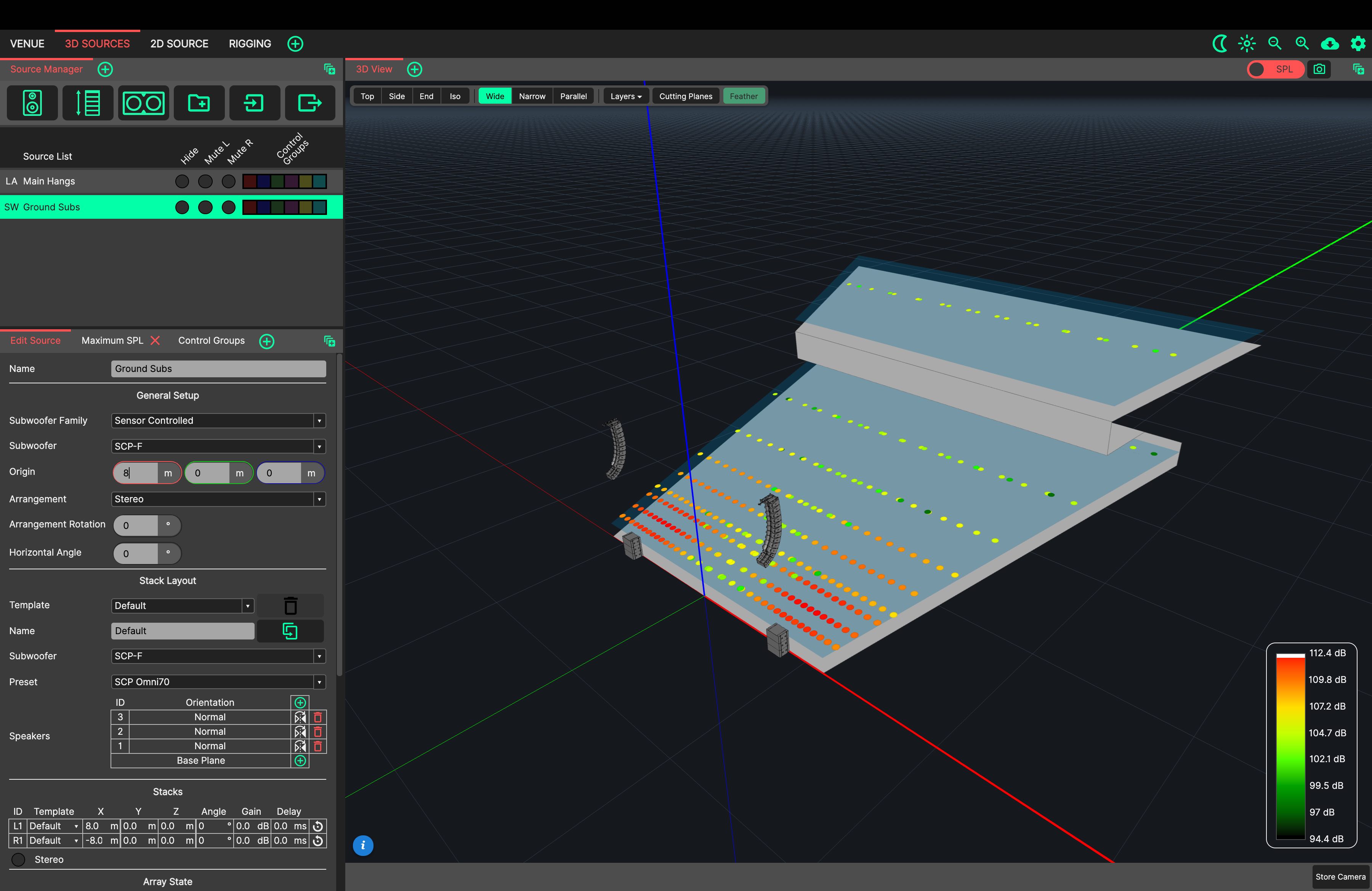
Change the arrangement to stereo and the HSA’s origin to: X = 8, Y = 0, Z = 0.
Add another SCP to the stack using the green ‘plus’ button in the Stack Layout table.
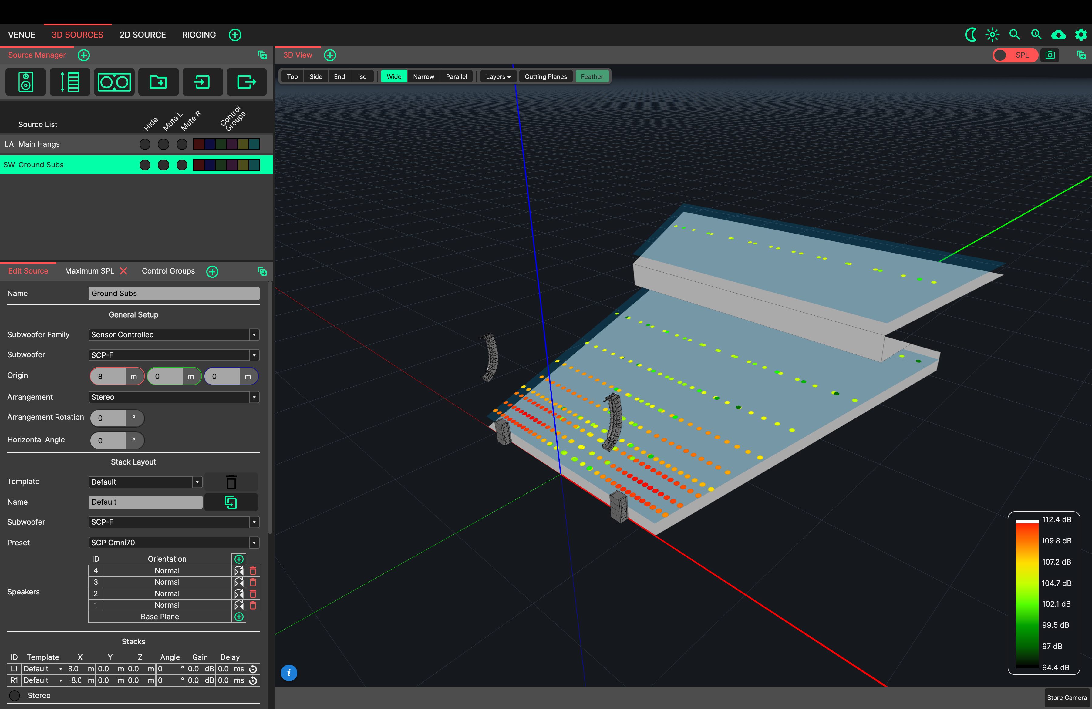
Now we can think about the system as a whole. Using the Microphones Panel, place a few Microphones in the 3D View.
Try muting and unmuting individual sources to see their complex summation.

Let’s align our Main Hangs to our Subs using Microphones.
Unmute only the left Main Hang, and the left Subs.
A cancellation can be observed around 50Hz.
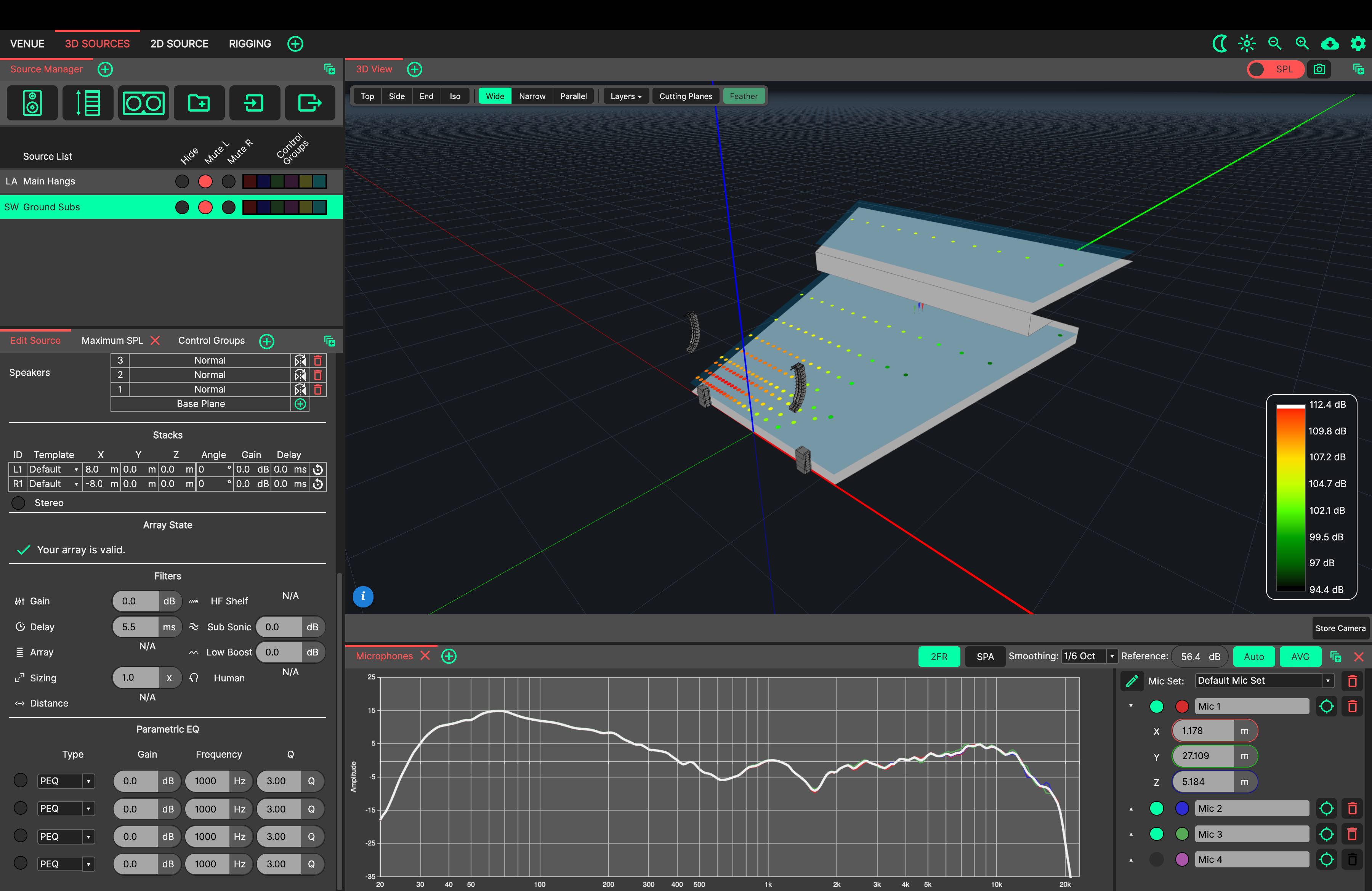
Add delay to the subs to align them. Watch the comb filter move as the delay is adjusted. The sources are aligned when summation is best.
In this case, 7.5ms has been added to the Subs.
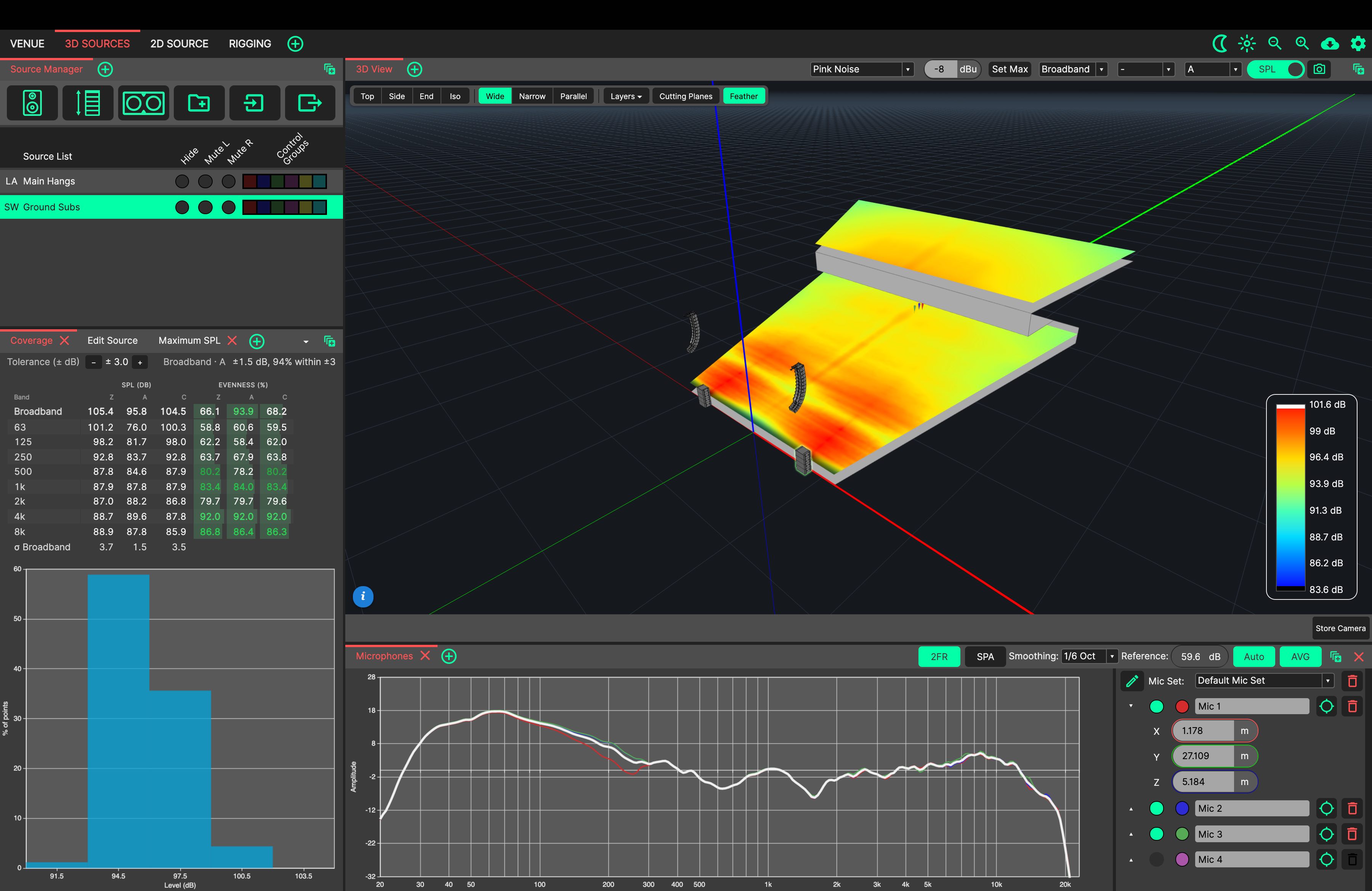
Lastly, SPL Mapping can be switched on in the 3D View for a detailed calculation. This can be used to further refine the design and evaluate a system’s performance. Click ‘Set Max’ beside the stimulus to see the maximum level the system can achieve.
To check whether every seat hears the same tonal balance, choose ‘Tonal’ in the band dropdown for Tonal Mapping.
You can add a ‘Coverage’ window to the 3D Sources tab, to view coverage and evenness metrics of the system as designed.