Microphones (Panel)
In the same way as measurement microphones can be used to determine a transfer function in real life, mics can do the same thing within System Optimiser. Mics placed within the 3D View show the complex summation of all loudspeaker sources within the 3D Scene that are currently unmuted.
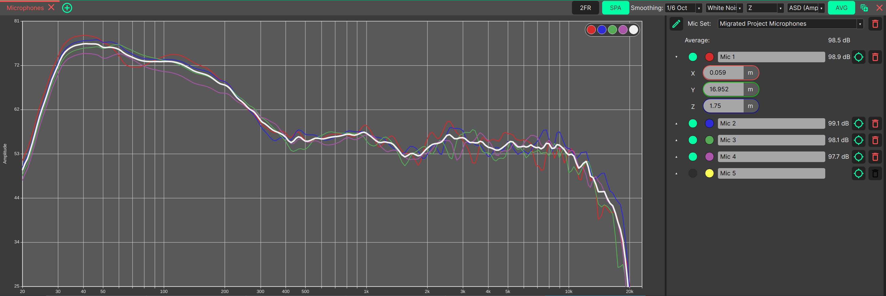
Microphones are displayed in a list on the right-hand side of the Microphones Panel. Clicking the green ‘crosshairs’ allows a new microphone to be placed in the 3D View by clicking on a layer.
Clicking the red ‘bin’ will delete a microphone.
‘Expanding’ a microphone using the arrow in the microphones list allows for precise location input. Microphones can also be assigned custom names (like “FOH”, “Stage”, etc…)
Microphones features both 2FR and SPA modes. The following operation is identical for both modes:
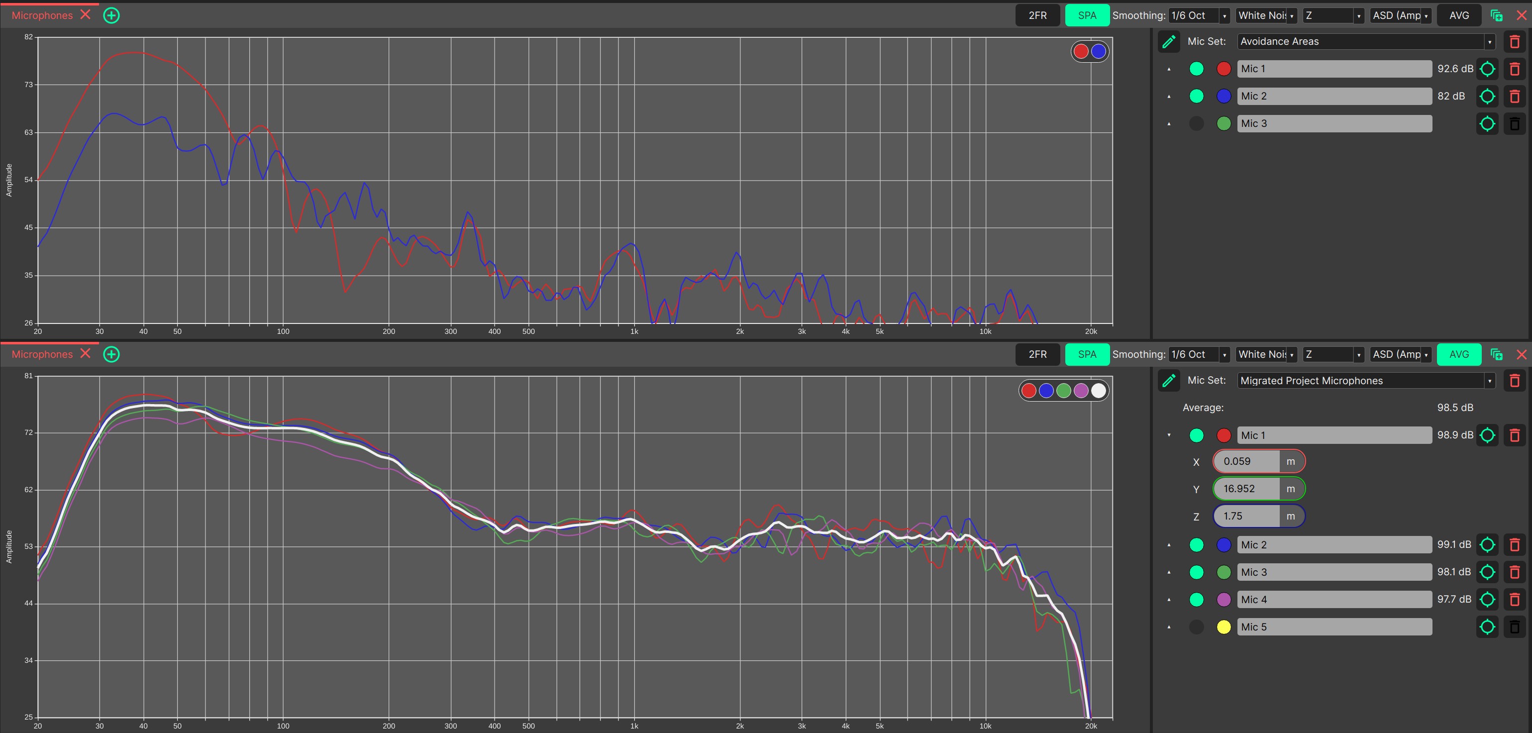
Smoothing for the graph can be adjusted using the drop-down list in the top-right of the Microphones Panel. To simplify the design process, an average curve of all shown traces can be shown by enabling the ‘AVG’ button. The average curve is plotted in thick white to make it stand out. The colour of the displayed traces will follow the global colour scheme, and will use a custom colour scheme if one is applied.
SPA Mode
The SPA Mode is the main mode of operation for Microphones. It can be imagined as grabbing an Acoustic Analyzer / Sound Pressure Meter, playing back the stimulus at the calculated level into the system and then looking at the results. Sound pressure levels in SPA Mode are directly influenced by the settings made in the Maximum SPL / Headroom Panel panel.
In the dropdown menu in the header, different stimuli can be selected for plotting, depending on the tuning goals and objectives.
Additionally, a weighting (Z / flat, A and C) filter can be selected. You will immediately see the effect of the weighting filter on the plotted responses.
Users can choose between different banding modes for plotting:
ASD (Amplitude Spectral Density)
1/24 Oct
1/3 Oct
1 Oct
For a more in-depth discussion of the background, please refer to the SPA section. To cut a long story short, ASD behaves more like a transfer function and is the square root of the PSD (Power Spectral Density). This means that in ASD mode, assuming a perfectly flat system response, White Noise will be flat and Pink Noise will be a straight line (due to the logarithmic scale). In any fractional octave mode, White Noise will get ‘louder’ with increasing frequency, while Pink Noise will have a ‘flat’ response (again, assuming perfectly flat system response).
Values shown in SPA mode are by default RMS sound pressure levels. If you need peak levels, please refer to the Preferences.
In SPA mode, each microphone microphone (and the average curve) has an additional sound pressure level assigned in the panel on the right side. This is the broadband or total sound pressure level for the selected stimulus, smoothing and weighting. Please do not use those sound pressure levels to assess the possibility for hearing damages (Disclaimer)
CODA has decided to not implement yet another mode of showing SPL Levels which is called Octave smoothing / sweeping in ARTA or Banding in Smaart. We believe this mode is highly misleading as it performs the Fractional Octave Band calculation not at discrete standard frequencies, but rather in a continuous / sweeping manner at all frequencies and thus gives the impression that there’s more power than there actually is, especially if you switch from e.g. 1/24 Oct to 1/3 Oct and the overall level increases.
2FR Mode
Operation of the 2FR Mode of Microphones is identical to the operation of 2FR Mode for Probes
Because 2FR mode is supposed to show a transfer function, the absolute SPL response of the system must somehow be normalised (level shifted). This is achieved by subtracting the value inside the Reference field from all curves. By default, this level is determined automatically by System Optimiser and the Auto button is selected. Determining where the 0dB line should be is a difficult question and is solved on a best-effort basis with a complex statistical analysis by System Optimiser. The automatically calculated Reference value can be overriden by deselecting the Auto button and entering a manual value.
2FR Mode is useful if you want to tune the system response, tonality or homogenity and maximum achievable sound pressure is not a primary goal.
Microphones should not be confused with Probes, which show only the on-axis response of a selected source.
As with all Panels, the Microphones Panel can be resized and moved using Panel Drag & Drop, and ‘popped out’ into an additional System Optimiser window. The location of this Panel will be saved as part of the current View Mode.