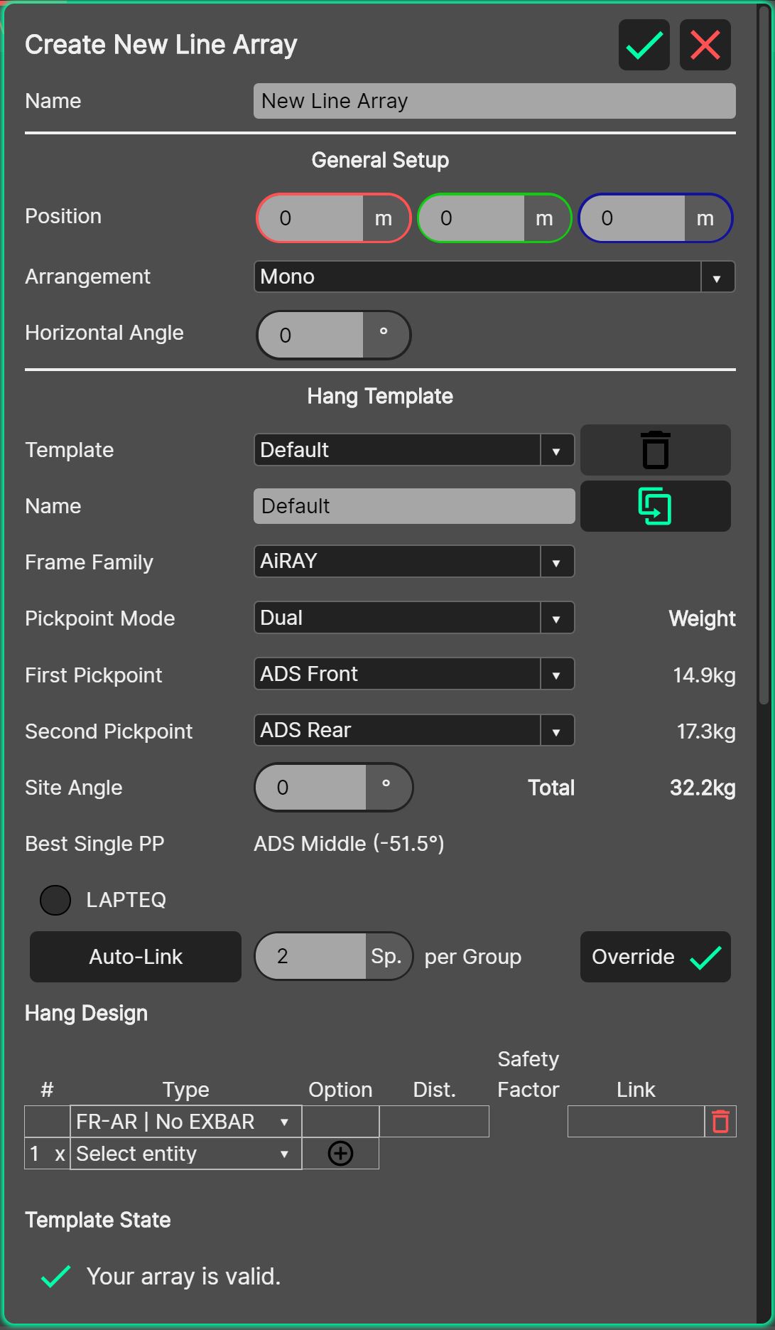
SVA Controller
This is the Standard Vertical Array Controller, which is used to adjust the parameters of new or existing SVA Sources.
- Name
A helpful name should be entered here to allow for easy recognition of the array within the Source Manager.
General Setup
Position: The position parameter defines the origin of the SVA. It is defined as the is the top, front, centre of the flying frame. When an arrangement (other than Mono) is used, the position of the controller is the centre-most position within the structure of the layout.
Arrangement: There are several arrangement strategies possible within the SVA Controller, from simply placing one array in the 3D View (Mono – which is the default strategy for a newly created SVA entity) through to more complex shapes like ellipses and rectangles. See the section on Source Arrangements for information about each choice.
Horizontal Angle: The horizontal angle parameter rotates the individual arrays about their local origin, around their Z-Axis. The horizontal angle parameter is mirrored from one source to the other, so with no transformations applied, the arrangement will be symmetrical about the global origin.
Hang Templates
Multiple templates can exist, to allow different loudspeaker configurations at different locations along the path set by the controller’s arrangement. See the section about templates for more information.
Template: By default, there is only one template, named ‘Default’. This default template contains the parameters of the array(s) that are placed at every location along the arrangement path. This default template cannot be deleted. Create a new template by selecting ‘New Template’ from the bottom of the drop-down list. Delete a template using the red ‘trash bin’ icon.
Name: A helpful name should be entered here to allow for easy recognition of the template within the hang layout table below.
Frame Family: The loudspeakers that comprise the line array added with the SVA controller are determined by the flying frame that exists at the top of the array. Adjust the frame family parameter to choose which flying frame exists at the top of the array, and thus which loudspeakers are able to be hung below it.
Pickpoint Mode: There are two methods of suspension handled within System Optimiser, dual pickpoint and single pickpoint. With dual pickpoint suspension comes the ability to directly choose the site angle which is adjusted in real life by shifting the balance of lift between the two pickpoints. In single pickpoint mode, the resultant site angle of the loudspeaker array is determined by the pickpoint in use, and the centre of gravity of the load hung beneath the frame.
- Dual Pickpoint Mode:
First Pickpoint: The first pickpoint parameter will allow the choice of the first (or downstage-most) pickpoint. The drop-down list will show the list of possible values for the frame family selected, together with any hardware (such as EXBARS) fitted to the frame.
Second Pickpoint: The second pickpoint parameter will allow the choice of the second (or upstage-most) pickpoint. The drop-down list will show the list of possible values for the frame family selected, together with any hardware (such as EXBARS) fitted to the frame.
Site Angle: The site angle parameter will adjust how the loudspeaker array is aimed in the up / down sense. Positive site angles will result in the loudspeaker array pointing up, whereas negative values will result in the loudspeaker arrays pointing down.
Best Single PP: The best single pickpoint readout provides an indication of what the best choice would be for the single pickpoint suspension method, should it in fact be used. The delta, or offset between the desired site angle & site angle that would result should the best single pickpoint be chosen is shown.
Weight: The weight information for each pickpoint is shown next to each pickpoint, together with the total weight for the entire array, to the right of the site angle parameter.
Note - The weight information shown is solely for the entities within the hang design table. No weight is added for cabling, top rigging, chain hoists or other accessories of any kind. It is the user’s responsibility to ensure the safety of the flown system at all times, and ensure that the correct total weight including all chain hoists / cabling etc is used for structural calculations.
- Single Pickpoint Mode:
First Pickpoint: The first pickpoint parameter allows the choice of pickpoint used to suspend the entire array. The choice of this pickpoint, together with the centre of gravity of the elements underneath (determined by type, quantity and angles of elements) determines the resultant site angle of the array. The dropdown list, when expanded, will show both the possible values for the frame family selected and accessories and the resultant site angle should that entity be chosen.
Site Angle: When single pickpoint mode is in use, the site angle parameter is a read only parameter, as the angle is adjusted by the choice of pickpoint, together with the influence of the elements hung below it. Positive site angles will result in the loudspeaker array pointing up, whereas negative values will result in the loudspeaker arrays pointing down.
Weight: The total weight of the entire array suspended on the pickpoint is shown to the right of the first pickpoint parameter.
Note - The weight information shown is solely for the entities within the hang design table. No weight is added for cabling, top rigging, chain hoists or other accessories of any kind. It is the user’s responsibility to ensure the safety of the flown system at all times, and ensure that the correct total weight including all chain hoists / cabling etc is used for structural calculations.
LAPTEQ: The LAPTEQ toggle button will cause a laser to be drawn from the frame at the location the laser would be mounted to the frame in real life, to see where in the venue the laser will be aimed at (if the frame supports a laser mount).
Link Group System: The link group system effectively defines the way in which the loudspeakers within an array are connected. This includes the electronic (amplifier) preset applied, and the HF Shelf and Distance Filter applied to each group.
Auto-Link: The Auto-Link tool, when enabled, will attempt to automatically link the loudspeakers within the hang design table to the strategy defined in the ‘Speakers per Group’ input box. When the Auto-Link button is engaged, it is not possible to remove loudspeakers from the link groups within the hang design table, only change the assignment, or add a new assignment.
Speakers per Group: The speakers per group button defines how many loudspeakers will be added to each link group with the Auto-Link tool.
Override: If changes have been made to either the Speakers per Group field since the Auto-Link button was engaged, or to the link group settings within the hang design table, pressing the override button will reset these to the Auto-Link strategy.
Hang Design Table
The Hang Design table is where entities are chosen for the loudspeaker hang, together with their options – E.G: the amount of which type of enclosures, with which angles between them and how they are connected.
# (ID Number): The ID field performs two functions:
If the ID contains just a number, the cell is acting as a read-out value of the ID number of the entity within the line array.
If the ID contains a number and an ‘x’ – the cell is acting as an input cell, whereby it is possible to choose the quantity of loudspeakers of type ‘Type’ that are desired to be added to the hang design table by pressing the green ‘plus’ button in the option cell.
Type: The type field determines which type of loudspeaker or flying frame / accessory is assigned to which entity within the hang layout table.
Option: The Option field performs two functions:
If the option field contains a number with a drop-down handle, the cell is acting on an entity that exists within the array already, and is choosing the inter-element angle.
If the option field contains a green ‘plus’ icon, the cell is acting in the ‘add element to table’ mode, where the Quantity of loudspeakers set in the ID cell, of Type set in the Type cell will be added to the hang layout table.
Distance: The distance field is a read-only field that shows the distance of the entity from its local origin to the audience ear layer it is pointing at, or the floor base plane. In the event that the element is not pointing towards an audience ear layer or the floor, a dash will be displayed. This is not an issue per se, as it is common for loudspeakers to overshoot audience ear layers, either for off-axis coverage, or for coupling reasons – but it is a prompt that no distance filter is being applied in the Link Group, so a manual input is required should it be desired. If the distance between different instances (e.g. left and right) of the particular template is too large, a yellow warning triangle will be displayed. The user should consider creating a new template and assign it to the instances separately
Safety Factor: This column contains the safety factor for each element in the array. For more information about rigging calculations, please refer to Rigging Calculations.
Link: The link cell contains the ID number of the Link Group that the loudspeaker is assigned to. There is a dropdown list where it is possible to either select a link group that exists already, unlink the loudspeaker, or create a new link group for the loudspeaker. Remove a Link Group using the red ‘trash bin’ icon.
Bottom height and Bottom angle: In order to allow for quick verification of a deployed setup, System Optimiser calculates the bottom height and bottom angle. Bottom height is the distance in the vertical direction (z axis) between the last speaker and the floor (z = 0). It is measured from the bottom front of the speaker right where the fillet starts. Bottom angle measured from the bottom of the last cabinet and would be obtained by placing an inclinometer at the bottom of the speaker. In some cases, a yellow warning triangle may be displayed. This may happen in the following cases:
You have changed the position of one of the instances to which the template you are viewing is assigned. In this case, please go to the Rigging tab to obtain the bottom height for each instance (hang / stack) individually
The template you are viewing is not assigned to any instance (stack / hang). In this case, please assign the template to an instance.
Link Group Table
When loudspeakers have been added to an array in the Hang Design Table, the Link Groups list is populated with the resulting ‘zones’ of speakers.
Electronic settings and optimisation can be adjusted here.
# (Link Group ID): The Link Group ID column details the Link Group entities within the loudspeaker array, and is the method of determining which link group is being worked on. The numbers in these rows correspond to the numbers in the Link cells in the Hang Design Table.
Preset: The ‘Preset’ dropdown chooses which electronic (amplifier) preset is assigned to the link group in question. This preset will thus be applied to all loudspeakers in the Hang Design Table which are assigned to the corresponding link group.
Note – There is no error checking / handling for preset compatibility within a line array yet. This will come in time with the amplifier implementation; so at possible, it is theoretically possible to mix minimal latency (>>) presets with full DS-FIR presets within the same line array, which would produce very bad results. Don’t do this.. it wouldn’t make for a very fun day at work.
Distance: The distance readout shows the mean distance of all elements assigned to the link group. This is required for the auto-distance correction. If all the members of the link group have a warning triangle, meaning they have no distance information, this cell will read 0m. This cell serves only as a read-out of the mean distance and does not perform any processing as such. If the instances to which the particular template is assigned have different distances, a range like ‘7 - 12m’ may be shown. This is a prompt for the user to split up the offending instances to a separate template.
Final Distance Filter: The final distance filter shows the distance filter applied to the link group. Ordinarily, it will be set to the value of the ‘Distance’ of the link group cell to the left of it, however there may be some cases when this value is either too big or too small. There may be times when it is desirable to enter manual values for the distance filter. It is here that this is possible. If the final distance filter value has been adjusted from the automatic distance value determined by the ‘Distance’ cell, the row reset button to the far right of the link group table will turn green.
HF Shelf: The HF shelf tool allows for manual correction of the HF shelf electronic filter to the link group. This will be applied to all loudspeakers within the link group.
Reset Button: The reset button will be black with the day mode theme selected, and white in the night mode theme. If the Final Distance Filter or HF Shelf filter have been adjusted from their defaults within the link group, the button will turn green. Pressing this button when it is green will reset the Final Distance Filter to the same value as the Distance cell for this Link Group, and will reset the HF Shelf filter to 0m of correction.
Array State
Array warnings and errors are displayed here. A warning will cause the source to have an orange background in the Source Manager. An error will cause the source to have an red background in the Source Manager.
See the section about Array States and Warnings for more information.
Hang Layout Table
The hang layout table details the specifics of the loudspeakers generated by the arrangement tool.
It can be thought of in the following way - the arrangement tool at the top of the controller is used as a “constructor” to populate the hang layout table with the entities defined with the template system.
Using the hang layout table, it is possible to assign templates to entities, and override parameters generated by the arrangement tool manually. When a change has been made manually either to the layout, or the electronic filter settings, so that they differ from that of the arrangement tool (constructor), a reset button will turn green on the relevant row.
ID: The ID number within the hang layout table is the unique identifier for the entity within the table. The ID’s are labelled ‘left’ through ‘right’, with a centre entity if the ‘Hang Count’ is an odd number. The left and right orientation is if the loudspeakers were on the front of stage, as viewed from Front of House.
Template: The template system allows for the creation of different entities that can be placed along the placement path defined by the arrangement. This cell in the hang layout table is where the different templates are assigned to the different entities. The default template is set by default.
X / Y / Z: These parameters are the value of the origin of the entity along the corresponding axis, as defined by the arrangement tool above. It can be overridden by typing a new value in, or by highlighting and scrolling with the mouse.
Angle: This parameter is the value of the angular rotation of the entity about the Z-Axis as defined by the arrangement tool above. It can be overridden by typing a new value in, or by highlighting and scrolling with the mouse.
Gain: This parameter is the value of the gain of the entity. It can be overridden by typing a new value in, or by highlighting and scrolling with the mouse.
Delay: This parameter is the value of the delay of the entity. It can be overridden by typing a new value in, or by highlighting and scrolling with the mouse.
Reset Button: If any values (X / Y / Z / Angle / Gain / Delay) have been overridden by the user in the hang layout table, the reset button at the far right of the respective row will turn green. When this reset button is pressed, the data contained within this row within the hang layout table will be reset to the state that was generated by the constructor.
Reset All Button: To reset the entire table back to the state that was generated by the constructor, when any data is overridden, a ‘Reset All’ button is drawn below the hang layout table. Pressing this button will reset the entire hang layout table to the state created originally by the constructor.
Stereo Button: When the stereo button is pressed, all layout adjustments (X / Y / Z / Angle) will be mirrored within the table, that is they will be adjusted in the equal and opposite sense automatically.
Filters and Parametric EQ
Each source controller has access to the full set of Tuning Filters available across System Optimiser and Linus Control.
See the section about Tuning Filters for more information.